

By R. F. Ayers and A. Green
Summary
This report describes factors influencing the stability and control of very high-speed cars running on deserts.
List of contents
1. Introduction
2. Wheel loads
3. Stability in pitch
4. Stability in yaw
5. Solid wheels on desert – or rubber tyres on tarmac
6. Gust sensitivity
7. Dynamic pitch stability
8. Driving characteristics at supersonic velocities
1. Introduction
Is it a high-speed car? Or is it a very low flying aeroplane? When considering the stability and control of very high velocity cars, the answer is: neither. These vehicles have unique characteristics and their stability must be analysed from first principles.
Much has changed since the early jet cars of the 1960s. Access to computational fluid dynamics, CAD systems and low-cost instrumentation has transformed the field of land speed record attempts and it is now feasible to design cars that exceed the velocity of sound. Below is a summary of lessons learned from Thrust SSC and the JCB Dieselmax, which are being employed in the design of Bloodhound. Dieselmax, although not thrust-propelled, is included here because at its top speed of 350 mph the flow around the wheel/ground contact points locally exceeded the velocity of sound. Thus, Dieselmax genuinely qualifies as ‘transonic’ since this term is defined as ‘locally experiencing both subsonic and supersonic flows’.
2. Wheel loads
As a vehicle running by itself on a smooth surface without obstacles, there is only one object with which the high-speed LSR vehicle can have a collision, and that is the track surface – there is nothing else to crash into. Therefore, to avoid such a collision, the primary safety of the vehicle comes down to keeping all of the wheels on the ground, all of the time. You can’t have a crash with something you’re already resting on.
In the case of Bloodhound we aim to ensure that the download (due to gravity plus aerodynamic up/downloads) is predicted to be never less than 10 kilonewtons on each wheel. Thus, there is a margin to ensure that unexpected and transient loads (e.g. due to crosswind gusts, steering inputs, surface irregularities etc.) will never result in a wheel leaving the ground.
In a perfect world the wheel downloads would remain constant throughout the speed range. But in reality, this is not possible. Instead, the wheel loads need to remain positive (to avoid leaving the ground) and bounded (to avoid structural overload of the chassis or indeed the surface). The generic target we identified for Bloodhound was to bound the wheel loads to between 50% and 150% of the load due to gravity (from which the above 10kN minimum is derived). This target is simple to express but extraordinarily difficult to achieve across a speed range from zero to Mach 1.4 (1000+ mph). Nonetheless, it provided the essential objective that drove the 5+ years of aerodynamic research to establish Bloodhound’s basic shape.
An alternative approach to bounding wheel loads is to trim the vehicle using active aerodynamic surfaces (such as winglets) to adjust the vertical loads during the run. Having assessed the complexity of a suitable system to achieve this, and the huge negative implications for safety if it malfunctioned in any way at high speeds, we decided to take the longer route for Bloodhound, to find a shape that would stay on the ground by itself without active aero trimming.
3. Static stability[1] in pitch
In theory, a vehicle will remain on the ground if the total vertical down-load (the sum of gravity, aerodynamic forces, pitch due to thrust, pitch due to drag, etc.) acts anywhere within the trapezium shape defined by the wheel/ground contact points. In practice more stringent criteria apply, and the centre of download should act somewhere near the mid-point of the wheelbase or problems of stability and control are likely to result.
It is sometimes stated, erroneously, that it is the aerodynamic centre that controls pitch stability. The aerodynamic centre does indeed have significance, but in connection with dynamic stability (see Section 7).
4. Stability in yaw
This is where the differences between automobile stability theory and aircraft stability theory become apparent. An automobile is said to be stable if the centre of download is behind the centre of gravity as in figure 1. (i.e. the rear axle is experiencing more download than the front axle, generating more lateral grip and ensuring the car has understeer).

Figure 1
An aircraft is considered stable if the yaw centre of pressure is behind the centre of gravity (i.e. like an arrow) as in figure 2.
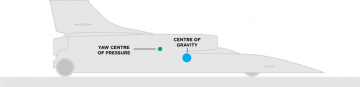
Figure 2
For a high-speed car both are significant, as automobile stability dominates at low velocities (since the aerodynamic forces will be small) but aircraft stability is massively dominant at high velocities. There will be intermediate velocities, likely to be in the region of 200mph to 400 mph, where they each make a significant contribution.
However, there could be a problem with the automobile component of stability of jet powered cars. Namely, that the automobile stability can be theoretically negative, so at first sight they should be difficult to drive at low velocities. The stability can be negative in the sense that the thrust-line of the jet engine is higher than the vehicle centre of gravity (since much of the vehicle mass is in the chassis and the wheels) thus generating a nose down pitching moment, so giving more download on the front wheel than on the rear. This nose-down moment will be increased by the influence of wheel drag on the surface making, the car even more unstable, as shown in figure 3.

Figure 3
The graph (Figure 4) illustrates the influence of the thrust line-of-action for Bloodhound. It shows the computed downloads for the front and rear pairs of wheels (in kilonewtons) against Mach number as the car accelerates up to a Mach number of 1.35. At Mach numbers below 0.62, front wheels experience greater downloads than the rear wheels due primarily to the high thrust line of the jet. According to the theory of stability for automobiles, this is clearly destabilising. At M = 0.62 the rocket ignites and its lower thrust-line restores (download-related) stability for the rest of the acceleration.

Figure 4
The question arises, does this theoretical instability matter? At low Mach numbers, say below about 0.2, the fin will not be providing much positive stability so one might expect the automobile instability to cause steering problems. However, we have personally met or communicated with drivers or designers from most of the jet/rocket powered cars since they began breaking records in the 1960’s. None of them referred to problems of directional instability on deserts. (One exception – Thrust 2 did suffer serious steering problems when its metal wheels were badly affected by conditions on a rutted Bonneville salt surface, but no steering problems were subsequently experienced on Black Rock Desert’s more compliant dry mud lakebed). We infer from this that the rate of divergence of these very long vehicles is sufficiently slow that the driver’s reflexes can correct for any steering deviation – probably without the driver even realising that the car is unstable. Thus, we appear to be in the region described as ‘unstable but controllable’. A bicycle is another vehicle that is unstable but still controllable even at low speeds.
Will yaw instability present a difficulty for Bloodhound in this velocity range? With a wheelbase of 8.9 metres there should not be a significant problem. The first runs into this velocity range will still be treated with appropriate caution – just in case.
As the velocity increases, the aerodynamic component of yaw stability becomes increasingly dominant. At this point, the key parameter for yaw is the yaw static margin, i.e. the distance between the centre of gravity and the aerodynamic centre in yaw. It is essential that the yaw static margin is positive as speed increases (if the static margin is negative, the vehicle will try to swap ends, an effect that would increase with speed until it overwhelms all other forces and the driver loses control).
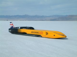 What is the ideal value for yaw static margin? For Dieselmax we aimed for 2% to 3% of the wheelbase. This worked well in a gusty crosswind and is the target figure for Bloodhound. This may not be easy to achieve since yaw static margin varies significantly during the course of a run due to fuel consumption moving the centre of gravity and the yaw centre of pressure varying with Mach number. Experience will show us what works best.
5. Solid wheels on desert – or rubber tyres on tarmac
The above analysis makes no reference to the type of surface the vehicle is traversing, but solid wheels on a desert will have very different characteristics from rubber tyres on a road. For instance:
(a) The unyielding shape of the aluminium wheel must sink into the desert surface. Experiments have shown that Bloodhound wheels will sink about 7 to 8 mm into Hakskeen desert surface at low velocity. Computations show that at 1000 mph the wheels will ‘plane’ at a depth of about 3 mm, so surface compliance will provide little assistance to the suspension. Rolling resistance will be some 2 to 3 time greater than for rubber on tarmac throughout the velocity range.
(b) The lateral constraint on a solid wheel by the desert is still a matter of conjecture, but clearly it will be much less than for a rubber tyre/tarmac contact. Crude experiments at low velocity show that the desert structure breaks away for any lateral load greater than about 0.35g to 0.4g. At still lower sideloads, it is not clear whether lateral constraint will exhibit the characteristics of viscous friction or of some other compliance law. As the car accelerates towards 600 mph the desert fluidises at the wheel contact points, which clearly will reduce the lateral grip still further, so the handling characteristics will be constantly changing.
(c) Rubber tyres on tarmac generate increased lateral grip as the download increases. It is quite possible that solid metal wheels running on a desert race track will also create higher lateral grip at higher downloads, but this effect is not quantified, or indeed certain. It is quite likely that the extra lateral grip generated by increased download is relatively small – this may provide part of the explanation of why ‘unstable’ LSR cars described above do not appear to be difficult to drive, as the destabilising forces involved could be relatively small.
(d) The performance of Thrust SSC was severely impaired by spray drag caused by an underbody shockwave penetrating the porous desert and kicking up loose sand which impinged on the rear structure and suspension. Bloodhound has been designed to minimise this problem.
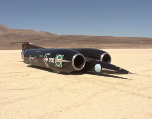
These problems were not insuperable for Thrust SSC, so presumably we can again overcome them for Bloodhound.
It is worth noting that wheel-driven vehicles suffer an additional complication, in that the driven wheels are providing some (possibly all) of their grip to traction, leaving nothing for lateral stability. This was not a major concern for Dieselmax as it was 4-wheel drive. To provide further confidence, the power to the rear wheels was limited to make sure that rear wheel rpm did not exceed front wheel rpm, to avoid the possibility of spinning up the rear wheels and producing an oversteer moment. Clearly this is not a solution for 2-wheel drive vehicles, with rear-wheel drive vehicles always facing stability challenges at high power settings.
6. Gust sensitivity and yaw stability
When travelling at supersonic velocities, any crosswind gust would be experienced as being sharp-edged. Too much stability would jerk the car head-to-wind so can be just as problematic as too little stability. In considering the yaw static margin above, it is therefore not enough for it simply to be positive. It also needs to be carefully bounded, which leads to the above target of 2-3%. The problem is that yaw static margin is difficult to assess, without extensive (and expensive) computer modelling. Worse, it is almost impossible to measure objectively once the vehicle has been built and is running. However, experience with Bloodhound suggests a test approach that may be of use.
During the runway testing of Bloodhound in 2017, the car was tested on a runway (and at a time of year) where gusty crosswinds were the norm. In addition, the initial car testing was conducted without the tailfin fitted. Without the fin, the yaw static margin would clearly be negative. This was deemed acceptable, due to the low speeds (under 200 mph) and high-grip rubber tyres being used on the runway. Once the fin was fitted, the static margin became positive. The difference could clearly be seen in frame-by-frame post-run analysis of in-cockpit video. Without the fin, the crosswind gusts were blowing the nose downwind, followed rapidly by driver corrections on the steering wheel. Once the fin was fitted, gusts would cause the nose to move into the wind, with the driver’s corrections now in the opposite direction, downwind, to correct.
This use of in-cockpit video provides a cheap way to assess the yaw static margin throughout the speed range (which is otherwise pretty much impossible to measure), based on the way the car handles as the crosswind varies. For test runs without a crosswind, the effect can be simulated by putting a small ‘kick’ into the steering, to see how the car responds. We plan to use this technique, which is similar to methods for measuring aircraft stability, during the high-speed testing of Bloodhound.
If crosswinds effects are a concern, then one obvious precaution is to operate at times of day when calm conditions may be expected – such as early morning. On a long track, local observers will also be needed to warn of local weather conditions along the track (in addition to ensuring that the track remains clear of people and animals!). However, limiting the yaw static margin (and thus limiting the gust response) remains highly desirable, as it increases the range of conditions in which the car can safely be run.
7. Dynamic [2] pitch stability
The two possible modes of dynamic pitch instability are heaving and porpoising. The names are self-explanatory. Normal suspension damping should cater for these problems, but it is also nice to know that these possible modes of instability are not being forced. We understand that heave has been experienced by F1 cars, but although porpoising is a theoretical possibility we do not know if it has ever been recorded in practice.
Heave instability is controlled by the heave derivative (the measure of how vertical aerodynamic load changes with vertical chassis movement), which we have computed from our CFD. In the case of Bloodhound, the heave derivative is extremely small, so forcing would not occur.
Porpoising is controlled by the pitch derivative (the measure of how vertical load changes with pitch angle). For Bloodhound, our CFD shows that the point of action of lift increment due to a change of pitch attitude (i.e. the aerodynamic centre) is well behind the centre of gravity and so is stabilising. Although there is a need to fit front winglets to cope with any possible front-end trim problems, they must not be larger than is necessary as this could lead towards porpoising instability.
It is also interesting to note that for an aeroplane, having a positive static margin (i.e. with the aerodynamic centre behind the centre of gravity) provides static stability but on the suspension-constrained Bloodhound, it provides dynamic stability.
8. Driving characteristics at supersonic velocities.
In the Introduction the question was posed of whether, at supersonic velocities, Bloodhound will behave like a high-speed car or like a very low flying aircraft. It is neither of these. At high velocity, the desert surface will fluidise under wheel contact so lateral wheel forces are expected to be minimal. Steering will be provided by the aerodynamic forces on the steered front wheels, while the fin provides the yaw stability. Thus, the dynamic yaw response of Bloodhound will probably feel like that of a supersonic hovercraft, or a supersonic hydrofoil, if such things existed. As they do not, we will have to explore the handling characteristics in step-by-step testing, with gradual speed increases to limit the magnitude of any changes, just as we did with Thrust SSC.
Provided we remain focussed on maintaining our key requirements of positive and bounded wheel downloads, and a positive and bounded yaw static margin, we can ensure that the car will remain firmly on the ground and pointing the right direction. This in turn will enable us safely to explore (and refine) the performance and handling characteristics of the vehicle. In this respect, any suitably cautious attempt to set a new world land speed record combines the best of experimental research with the ultimate in motor racing.
[1] Static stability is the tendency to return to the neutral position when the vehicle is displaced. Put simply, if a displacement caused the vehicle to diverge, it is statically unstable, while if it returns to the neutral position, it is said to be statically stable.
[2] While static stability is a measure of whether a vehicle will return to a neutral position, dynamic stability is the measure of how it will do so. If it settles straight back to equilibrium it is dynamically stable, if it oscillates about the neutral point it has neutral dynamic stability and if it suffers divergent oscillations it is dynamically unstable.


